
Understanding Kube-OVN CNI
Kube-OVN connects Kubernetes Pods using Open Virtual Network (OVN) and Open vSwitch (OVS). It allocates Pod addresses, builds logical networks, and implements network policies and Service load balancing.
This page explains Kube-OVN architecture, logical networks, configuration updates, and common traffic paths. It also provides component inspection examples and links to configuration guides.
TOC
Network Modes and ScopeArchitecture and ComponentsControl plane componentskube-ovn-controllerovn-centralNode componentsovs-ovnkube-ovn-cniMonitoring and optional componentskube-ovn-pingerkube-ovn-monitorkube-ovn-speakerComponent deploymentLogical NetworkLogical switches and subnetsIP address allocation and Subnet selectionThe join switch and the node interfaceOverlay encapsulationGateway modesNetwork isolation and access controlHow a Network Change Becomes a FlowTraffic PathsPod to Pod on the same nodePod to Pod across nodesPod to a ServicePod to a node or an API serverPod to an external networkHigh AvailabilityInspecting Components in Your ClusterList workloadsLocate Pods and containersInspect rollout state and eventsResource usage and limitskubectl-koNext StepsNetwork Modes and Scope
Kube-OVN supports overlay and underlay Subnets. The mode determines how Pod traffic reaches other nodes and the physical network.
The traffic-path diagrams in this page describe an overlay network in the default VPC with Geneve tunnels. The Service diagram also assumes that OVN Service load balancing is enabled for the controller and the source Subnet. Names and CIDRs shown as defaults can differ from your cluster configuration; check the Subnet settings and the installed Kube-OVN configuration with your administrator.
Architecture and Components
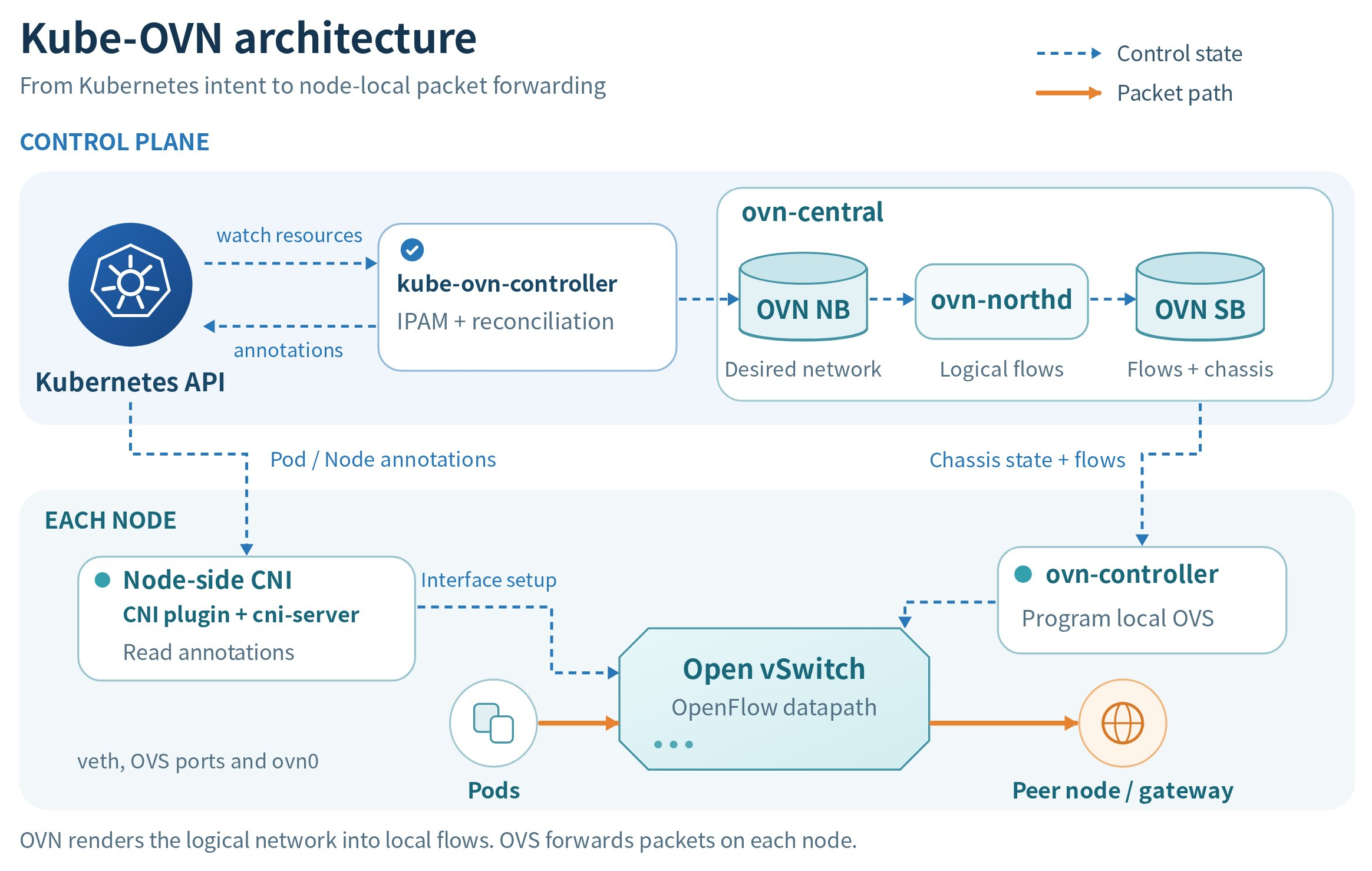
The control plane maintains the desired network and translates it into forwarding rules. Node components connect Pod interfaces and realize those rules in OVS. Monitoring and optional components provide health information and external integration.
Control plane components
kube-ovn-controller
The kube-ovn-controller Deployment watches network-related Kubernetes resources, including Pods, Services, EndpointSlices, Nodes, NetworkPolicies, VPCs, Subnets, VLANs, and ProviderNetworks.
It allocates Pod addresses, writes logical ports and the required routes or policies to the OVN northbound database, and records assigned network information in Pod annotations for the node agent.
ovn-central
The ovn-central Deployment runs the OVN control plane services in its ovn-central container:
ovn-nb: The northbound database stores the desired logical network, including switches, routers, ports, ACLs, and load balancers.ovn-sb: The southbound database stores logical flows, datapath and port bindings, and chassis state.ovn-northd: Translates northbound configuration into the logical flows and related records used in the southbound database.
For upstream implementation details, see the OVN architecture. For the effects of component failures, see High availability.
Node components
ovs-ovn
The ovs-ovn DaemonSet runs an openvswitch container on each eligible Linux node. The container includes the local OVS database, ovn-controller, and ovs-vswitchd. The OVS database holds bridge and interface configuration, ovn-controller programs the forwarding rules, and ovs-vswitchd manages packet forwarding through the OVS datapath.
kube-ovn-cni
The kube-ovn-cni DaemonSet runs a cni-server container on each eligible Linux node. Its install-cni init container installs the kube-ovn CNI plugin and supporting binaries into the host's CNI binary directory (/opt/cni/bin by default), and writes the CNI configuration to /etc/cni/net.d by default. The container runtime invokes the kube-ovn plugin, which sends CNI requests to the local cni-server.
The node-side CNI plugin and cni-server work together to:
- Configure Pod interfaces, IP addresses, and routes during CNI ADD, and remove the corresponding attachments during CNI DEL.
- Attach Pod interfaces to OVS ports and maintain their local network configuration.
The cni-server daemon also maintains node networking by:
- Continuously reconciling host gateway filtering, NAT, and routing rules.
- Creating and configuring
ovn0to connect the host network to the default VPC.
Additional node-network configuration has its own requirements. See Prepare the underlay physical network and Cluster Interconnection (Alpha).
Monitoring and optional components
kube-ovn-pinger
The kube-ovn-pinger DaemonSet runs a pinger container on each eligible Linux node to collect OVS status information and probe network connectivity and latency.
kube-ovn-monitor
The kube-ovn-monitor Deployment collects OVN status information and metrics. In the standard deployment, it runs on a node selected for OVN central services.
kube-ovn-speaker
This optional DaemonSet runs on nodes selected for BGP advertisement and publishes routes to the external network, allowing external access directly through Pod IPs. For installation and BGP options, see Configure BGP.
Component deployment
The following table describes a standard ACP installation with the OVN control plane in the same cluster. The Kubernetes workloads use the kube-system namespace by default. If your installation uses another namespace or a separately hosted OVN control plane, use its actual namespace and workload configuration.
Node selectors, affinity, and tolerations determine which nodes are eligible. Deployment replica counts depend on the installation; a DaemonSet places a Pod on each eligible node. The optional speaker is installed separately as described in Configure BGP.
For commands and actual example outputs, see Inspecting components in your cluster.
Logical Network
OVN models the cluster network as logical switches and logical routers, and Kube-OVN maps its Kubernetes resources onto them. A VPC groups Subnets under its logical routing configuration. The following diagram shows the default VPC, including the join switch that connects it to the hosts. Custom VPCs have their own logical routers and require their own routing and external connectivity configuration. For resource fields, see the VPC API reference.
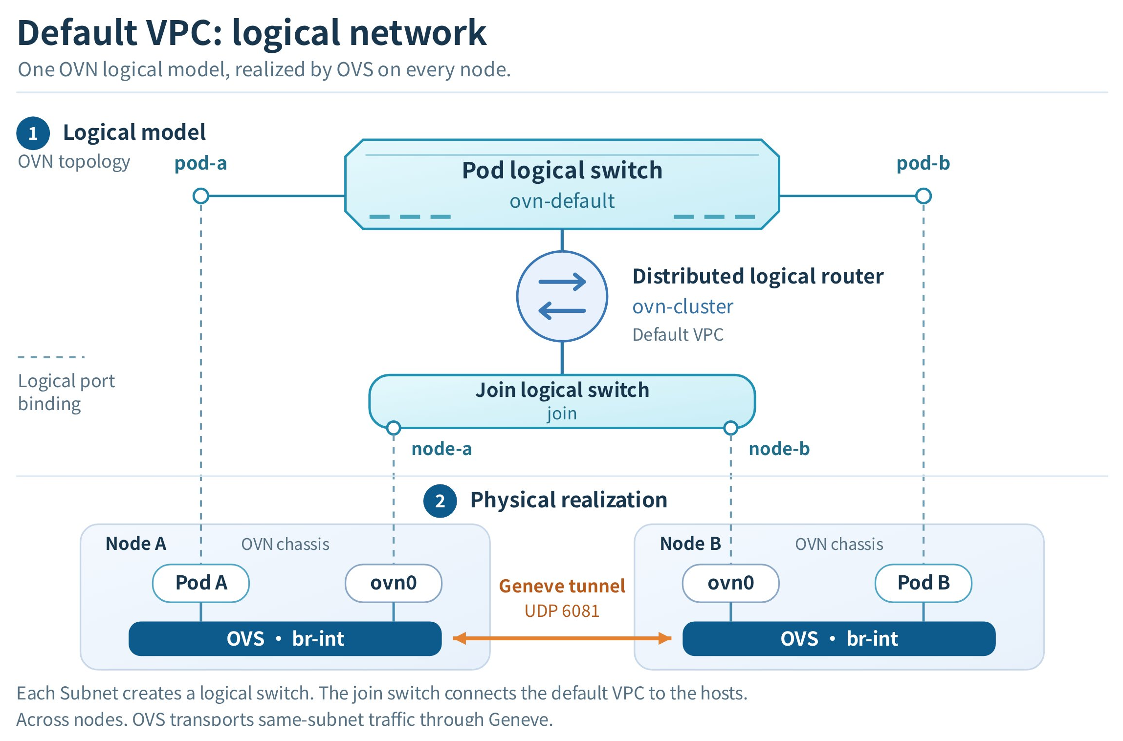
In this default VPC overlay network, Pods attach to their Subnet's logical switch, the Subnet gateway connects that switch to the VPC logical router, and join connects the router to the nodes' ovn0 ports. OVS implements the logical switching and routing on the nodes. Cross-node overlay traffic uses tunnels; traffic destined for a host or an external network leaves the overlay through the appropriate node interface. The sections below describe each part.
Logical switches and subnets
Each OVN-managed Subnet is backed by one logical switch. Pods attached to the Subnet become logical switch ports. A Namespace can have its own Subnet or share one with other Namespaces.
kube-ovn-controller allocates Pod IP addresses from the selected Subnet. The MAC address can be specified for the Pod or generated by IPAM. The controller records the assigned IP and MAC addresses, along with the Subnet CIDR, gateway, and logical switch, in Pod annotations. The node-side CNI components use this information, together with any additional route configuration, to configure the Pod interface and routes.
The default Subnet ovn-default carries the Pod network in a standard default VPC deployment. Custom VPCs have their own logical routers and Subnets. Attaching multiple interfaces to one Pod is a separate configuration described in Pod multi-network interfaces.
IP address allocation and Subnet selection
Kube-OVN allocates an address from the Subnet selected for each Pod interface it manages. For the primary network, the platform's project or Namespace binding determines the available Subnets unless the Pod explicitly selects a Subnet. Without an explicit selection or binding, Pods use their VPC's default Subnet. For the platform allocation rules, see Configure Subnets.
When planning addresses, consider the following:
- Available addresses: The Subnet CIDR defines the address range. Reserved addresses in
excludeIpsare excluded from automatic allocation; reserving an address does not assign it to a Pod. - IP pools: An IPPool restricts allocation to a set of addresses within a Subnet. Namespace or Pod settings select the pool. Running out of addresses in the eligible pools does not mean the Pod can use the remaining addresses elsewhere in the Subnet.
- Address exhaustion: If no eligible address is available, Pod network setup cannot complete. Check the Pod events and the available addresses in its selected Subnet or IPPool.
- Pod replacement: A replacement Pod is not guaranteed to receive the previous Pod's address through automatic allocation. Use a Service when applications need a stable access address.
Choose CIDRs and address families that match the cluster configuration. Check for conflicts with the node network, Service CIDRs, join, and external networks that the Pods must reach. For a secondary Pod interface, follow the separate Subnet and network attachment configuration in Pod multi-network interfaces.
The join switch and the node interface
Nodes are not part of a Pod Subnet. Kube-OVN connects each node to the overlay through a dedicated logical switch named join (CIDR 100.64.0.0/16 by default) and an OVS internal port named ovn0 on the node.
ovn0 connects the host network to the default VPC. kube-ovn-controller allocates the node an address from the join Subnet and records it in Node annotations; kube-ovn-cni reads those annotations to create and configure the interface. The Pod-to-node path below explains how traffic reaches a node or an API server endpoint on that node.
Overlay encapsulation
With the default Geneve network, OVS instances on different nodes are connected by tunnels. ovn-controller installs the forwarding rules, and OVS encapsulates cross-node overlay traffic in Geneve (UDP 6081) and sends it to the remote node's encapsulation address. The node network must allow this traffic between the participating nodes. See Configure the MTU for the encapsulation overhead this adds.
For underlay traffic, a VLAN Subnet connects to the physical network through a localnet port and the ProviderNetwork's node interfaces. Connectivity between underlay and overlay Subnets needs the appropriate routing configuration; see Automatic interconnection of underlay and overlay Subnets.
Gateway modes
For an overlay Subnet in the default VPC, gatewayType selects the nodes used for external egress. For Subnets in this VPC other than join, the controller sets an omitted gatewayType to distributed.
The logical router uses policy routes to direct that traffic to the selected node's address on the join switch:
- Distributed: each node acts as the gateway for the Pods running on it, so north-south traffic exits through the local node.
- Centralized: external egress is directed to selected gateway nodes. Multiple gateway nodes use active-backup mode by default; ECMP requires
spec.enableEcmp: true.
These modes govern external egress; traffic between Pods or to a Service is not automatically sent through a centralized gateway. See the external access paths below and Configure a centralized gateway.
Network isolation and access control
A Namespace or Subnet assignment determines where workloads belong and how they receive addresses. It does not, by itself, deny traffic to workloads in other Namespaces or Subnets. Subnets in the same VPC can communicate through its logical router when routes and access-control rules allow it.
Use the following controls for their respective purposes:
For standard NetworkPolicy, ingress and egress isolation are evaluated separately. When a direction is isolated, the traffic must be allowed by a policy selecting the Pod in that direction; a connection must satisfy the applicable rules at both ends. If cluster-wide policies or Subnet ACLs are configured, their actions and evaluation order also affect the result. See Network Policy and Network Policy APIs.
Pods using hostNetwork share the node network and do not have an ordinary Pod network interface on the Subnet. Do not use ordinary Pod NetworkPolicy assumptions to describe their isolation; check the node's access controls and the documented policy limitations.
How a Network Change Becomes a Flow
Kubernetes resources describe the desired network. Kube-OVN and OVN translate that configuration into progressively more detailed representations until each node has the OpenFlow rules needed to forward packets.
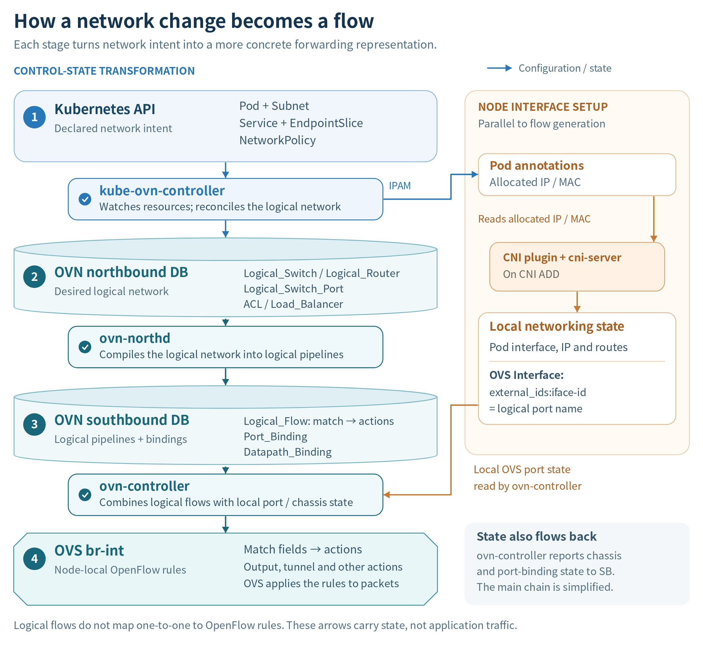
The arrows show configuration and state updates. Packet forwarding takes place in OVS on the nodes.
- Kubernetes resources to logical network objects.
kube-ovn-controllerwatches resources such as Pods, Subnets, Services, and NetworkPolicies. It reconciles them into the OVN northbound database (ovn-nb): logical switches, routers, ports, ACLs, and load balancers describe the intended connectivity. - Logical network objects to logical flows.
ovn-northdreads the northbound configuration and builds the logical processing pipeline in the OVN southbound database (ovn-sb).Logical_Flowrecords describe match conditions and actions;Datapath_BindingandPort_Bindingrecords identify the logical datapaths and ports. - Logical flows to node-local OpenFlow rules. The
ovn-controlleron each node combines southbound information with its chassis identity and local OVS interface state. It installs OpenFlow rules in the local OVS integration bridge,br-int, so OVS can implement the logical network on that node.
Pod interface setup supplies the local state needed by this process. During Pod creation, the node-side CNI plugin and cni-server work together to configure the Pod interface and OVS port using the assigned IP and MAC addresses. The OVS interface's external_ids:iface-id identifies the corresponding OVN logical port, allowing ovn-controller to associate that port with the node. ovn-controller also reports chassis and port-binding state back to the southbound database.
Administrators can inspect these layers with kubectl-ko.
Traffic Paths
The diagrams below describe the default VPC overlay network with Geneve tunnels. OVS executes the logical switching, routing and load-balancing rules installed by ovn-controller. NetworkPolicy and Subnet ACLs can allow or block traffic on these paths.
Underlay networks and custom VPC egress have different topologies. Use the network mode and scope of your deployment when interpreting these diagrams.
Pod to Pod on the same node
For two Pods in the same Subnet on one node, the packet travels from the source Pod interface through the local OVS bridge br-int to the destination Pod interface. The logical switch provides the forwarding rules; the packet does not use a physical NIC or a Geneve tunnel.
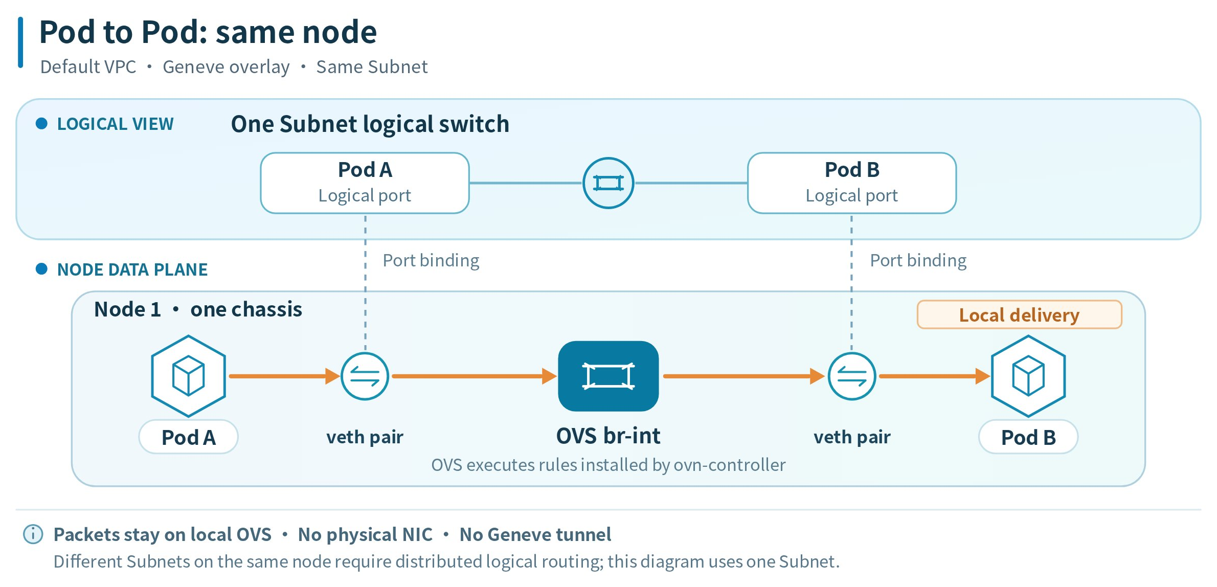
When the Pods belong to different Subnets in the same VPC, the VPC logical router provides the routing rules. OVS still processes the traffic locally when both Pods are on the same node.
Pod to Pod across nodes
For Pods in the same Subnet on different nodes, the logical switch connects their logical ports, which are bound to different node chassis. The source OVS encapsulates the packet in Geneve, sends it through the node network, and the destination OVS decapsulates it and delivers it to the destination Pod.
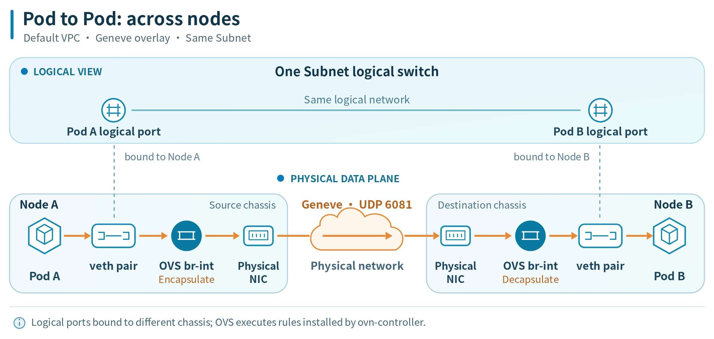
For Pods in different Subnets in the same VPC, the logical router also routes the packet between the Subnets. The cross-node overlay transport still uses the Geneve tunnel between the OVS instances.
Pod to a Service
When OVN Service load balancing is enabled for the controller and the Subnet, kube-ovn-controller maintains OVN load balancers on eligible Subnet logical switches. OVS translates the Service ClusterIP and port to a selected backend endpoint IP and target port. For a Pod backend, forwarding then follows the same-node or cross-node path above.
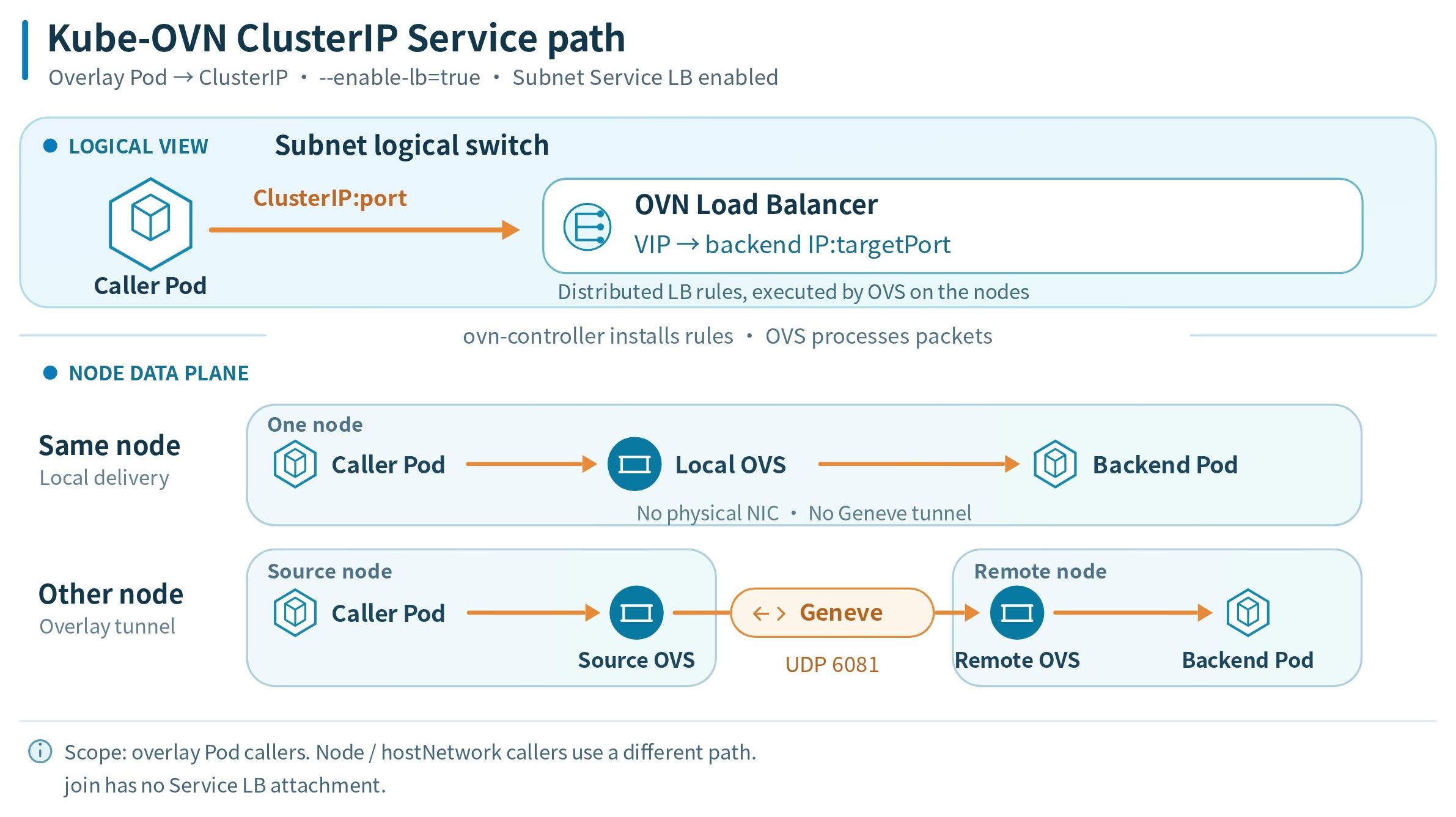
The join switch is excluded from OVN Service load-balancer attachment. The diagram covers ordinary overlay Pod callers with Pod backends. Other Service access scenarios have additional conditions:
For Service creation and exposure, see Configure Services. Before combining external access with a centralized gateway, check its NodePort and hostport limitations.
Pod to a node or an API server
For traffic to a Node InternalIP, the default VPC logical router uses a destination policy route to direct the packet to that node's address on the join switch. The packet reaches the target host through its ovn0 interface. Traffic to a remote node uses Geneve between the OVS instances; traffic to the local node stays local.
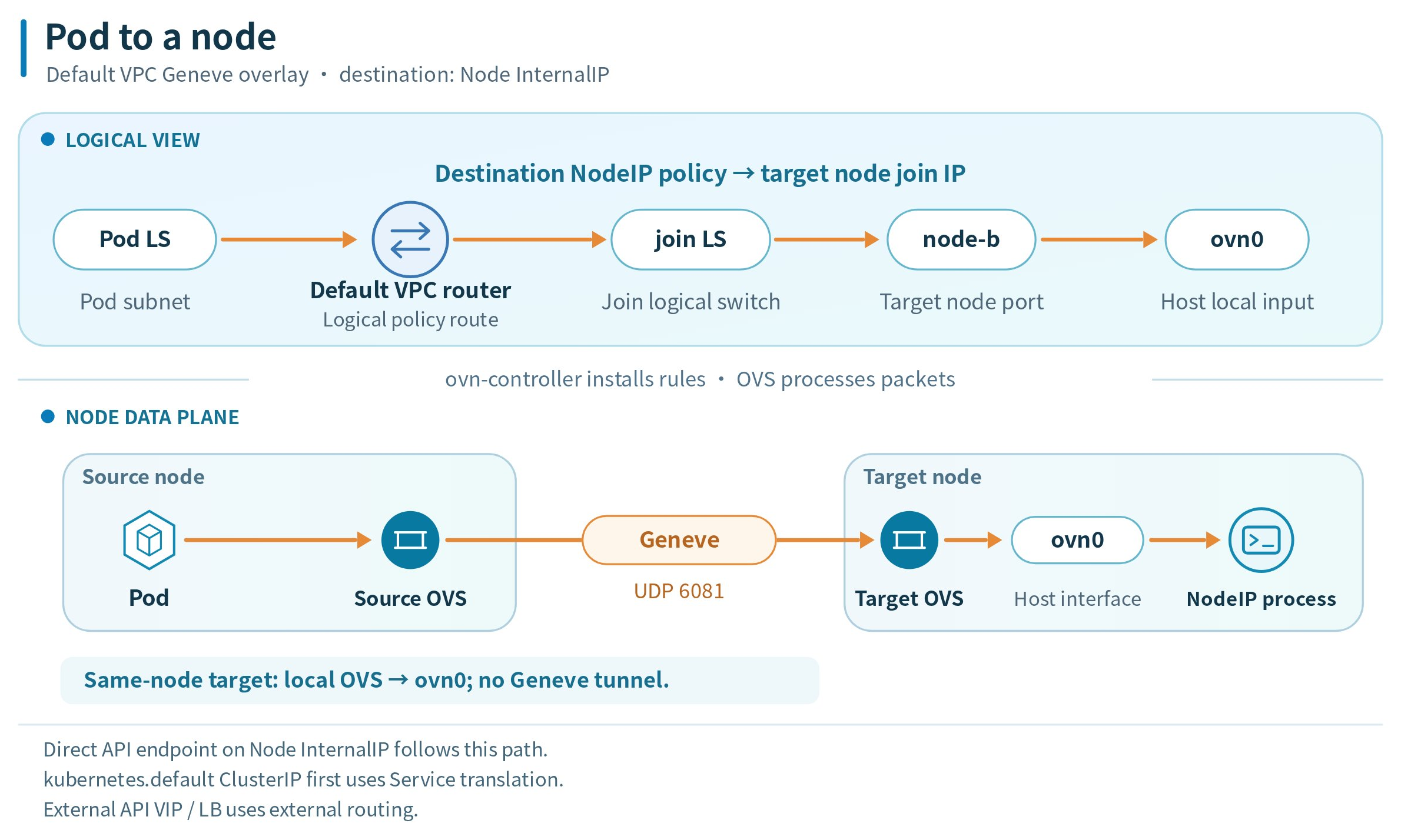
A direct API server endpoint on a Node InternalIP follows this node access path. Access through the kubernetes Service ClusterIP first translates the Service address to an API server endpoint; forwarding then follows the route for that endpoint. An API endpoint exposed through an external VIP or load balancer follows the external routing path instead.
Pod to an external network
The default VPC logical router uses a source policy route to select the egress node's address on the join switch. The packet reaches that node through ovn0, then follows the host's routing rules and egress NIC to the external network:
- Distributed gateway: traffic leaves through the Pod's local node.
- Centralized gateway: traffic leaves through a selected gateway node. When that gateway is remote, OVS transports the packet to it over Geneve. See Gateway modes for active-backup and ECMP behavior.
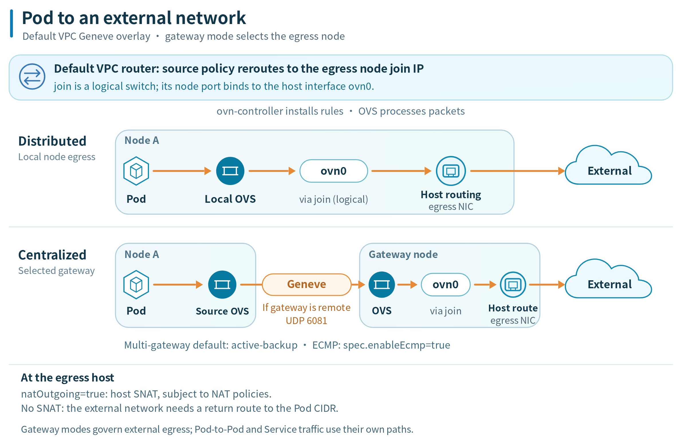
With natOutgoing: true, matching external traffic is source-NATed on the egress host, subject to configured NAT policies. If packets leave the egress host with their original Pod source addresses, the upstream network needs a return route to the Pod CIDR. See Configure a centralized gateway for gateway configuration. For workload-specific egress through dedicated gateway Pods, see Egress Gateway and its comparison with centralized gateways.
High Availability
In a high-availability deployment, ovn-central replicates the northbound and southbound databases with Raft. Each database needs a reachable majority of its members to commit updates. Database availability is one part of network availability: the controllers, node networking, and any selected gateway must also work.
When ovn-controller must reload network state after a restart, it needs access to the southbound database and then programs the local OVS. ovs-vswitchd does not read the southbound database directly. Connectivity can be interrupted while the node's interfaces and forwarding rules recover.
Inspecting Components in Your Cluster
Use kubectl configured for the target cluster and an account with permission to read these resources. The following example outputs were captured from a three-node test cluster running Kube-OVN v1.16.13. Replica counts, Pod names, node names, IP addresses, ages, and events vary by cluster; use them to understand the output rather than as required configuration values.
Long outputs are shortened to the key fields and representative rows discussed below. In excerpts, ... marks omitted lines; running the commands returns the full output.
List workloads
Example output:
Example output:
Check the Deployment READY column against its requested replica count. For each DaemonSet, compare DESIRED, CURRENT, and READY; after a successful rollout, the ready count should match the desired count for eligible nodes. In this example, ovn-central and kube-ovn-controller each have three ready replicas, kube-ovn-monitor has one, and each DaemonSet has a ready Pod on all three eligible nodes.
Locate Pods and containers
List the Pods to see their actual placement and runtime status:
Example output (excerpt; one Pod per component is shown):
The NODE column shows where each Pod runs. READY, STATUS, and RESTARTS help identify Pods that have not become ready or are restarting. The Pod selector for ovs-ovn is app=ovs; the other components in this list use their component name as the app value. An optional component that is not installed will have no matching Pods; kube-ovn-speaker is not installed in this example cluster.
For example, list the containers inside the OVN and OVS Pods:
Example output (excerpt; one Pod per workload is shown):
For the standard deployment, the CONTAINERS column shows ovn-central for the database Pods and openvswitch for the OVS Pods. NB, SB, and ovn-northd run as processes inside the ovn-central container; the node OVS database, ovs-vswitchd, and ovn-controller run inside openvswitch. They are not separate Kubernetes Pods or containers.
Inspect rollout state and events
To inspect rollout details and workload events, describe the workload. For example:
Example output (excerpt):
In this example, all three replicas are available, and the Available and Progressing conditions are True.
Example output (excerpt; repeated creation events are omitted):
Here, the desired, current, and available node counts are all three, and no Pods are waiting or failed. The SuccessfulCreate event shown records creation of one Pod. Events are transient, so an older workload can show Events: <none>; check current readiness as well as any events.
These queries show deployment and readiness state. Use the traffic paths and the linked configuration guides to check the behavior of a particular network connection.
Resource usage and limits
Insufficient memory can cause the openvswitch container to be OOMKilled; CPU throttling can delay network configuration and packet processing. Ask the cluster administrator to check resource usage when these symptoms occur.
The ACP Helm Chart uses ovs-ovn.requests and ovs-ovn.limits for resource settings. Its upgrade template reads CPU and memory values from the existing ovs-ovn DaemonSet, so administrators must also verify the effective resources on that DaemonSet when changing or upgrading the configuration.
kubectl-ko
This kubectl plugin lets cluster administrators inspect OVN databases and node OVS state. It wraps commands such as ovn-nbctl, ovn-sbctl, ovs-vsctl, and ovs-ofctl. Use the plugin version supplied for the installed Kube-OVN release and the permissions required to access its components.